Step
| Sub step
| Description
| Things to prep or look up in advance
|
Verify code is present
|
| If the symptom is not present, then it will be difficult to verify the fix.
|
|
Check all prep items are on hand
|
| Look at the "Things to prep" column
|
|
|
|
|
|
Set up the car
|
| Prepare any of the cars electrically operated mechanisms the way you will need them later when the 12V battery is disconnected, such as door locks, windows, trunk lid, e-brake etc.
|
|
Remove the HV battery disconnect
|
| This is presumably accessible from inside the car, ahead of the rear seat?
| -- Does this precipitate requirement to later perform some reset procedure?
|
| Disconnect 12V battery |
| May want to put a charger on the 12V battery while working on the other stuff, to make sure the 12V is charged ready for testing when reconnected..
| -- Before or after the HV battery disconnect? |
|
|
|
|
| Remove the battery pack | Raise the car | ... high enough to be able to get the battery out.
-- A lift is obviously preferable
-- Example of how to do it with jackstands etc: "A guide to swapping your Gen 1 Volt battery at home" https://www.gm-volt.com/threads/a-guide-to-swapping-your-gen-1-volt-battery-at-home.321946/
| -- Preferably a lift.
-- Jacks? Ramps?
|
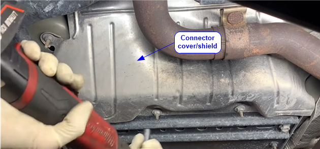
| Remove battery pack end cover
| Remove the sheet metal that covers the terminals and hoses at front of the battery pack
-- Video: 2013 Chevy Volt battery removal and installation https://www.youtube.com/watch?v=87kWRUB3grY
|
|
| Unplug connectors and hoses
| Disconnect the cable connectors and the coolant hoses. Plug the hoses and the inlet/outlets
If all goes well, there will be no need to drain the coolant further, so less to refill and get circulating..
| -- Pan to catch coolant
-- Rubber plugs for the coolant inlets and the coolant lines. (cheap assortments on ebay)
|
| Remove most bolts
| Remove most of the battery pack supporting bolts , leaving a few to hold up the battery without it sagging
| -- Metric sockets, probably 10mm or 13mm
-- Containers for saving and organizing removed nuts and bolts.
|
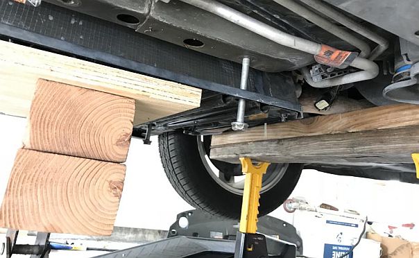
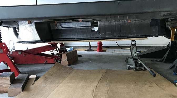
| Move support under battery
| If car on a lift, move a sturdy cart under the car, possibly with some 2x4s etc sized to receive the battery. Lower the lift to rest the battery on the cart and boards.
If car on ramps etc, raise a 2x4+ply platform jacked up on one or two floor jacks to support the battery.
| -- Devise the support platform ahead of time and make sure there's enough vertical clearance.
|
| Lower the battery
| Remove last few bolts
|
|
|
| If car on a lift, raise the car
If car on jackstands or ramps etc, Lower the jacks
. |
|
|
| Slide the battery out from under the car
|
|
|
|
|
|
| Move battery to work area
| -- Roll the battery to a convenient place to work on it.
-- Ensure that the whole length and width of the battery is well supported and not flexing. The bottom mounting plate under the battery a little bendy, so can allow the battery to flex undesirably. (The risk is in flexing the hoses between the big battery sections -- they are flexible, but no point unduly stressing their seals.)
|
|
|
|
|
|
Remove top battery cover
| Remove cover
| Lots of bolts.
Video: "Dissecting the Chevy Volt's electric drivetrain" https://www.youtube.com/watch?v=00tTckGUv7I
| Metric sockets
|
|
| I believe you also have to undo bolts or screws around the orange disconnect receptacle: https://youtu.be/00tTckGUv7I?t=85
| Torx bits I think.
|
|
|
|
|
Verify thermistor problem
| Unplug harness plugs
| On the rear battery section, leftmost module, unplug X4, the leftmost connector from the top of the battery.
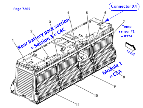
Video "2013 Chevy Volt Battery BMS Pinout Diagram" https://www.youtube.com/watch?v=5_cuqnSQE8c has useful visuals for the next couple of steps.
Video segment: https://youtu.be/5_cuqnSQE8c?t=271 for removing the plugs on top of the battery
|
|
| Measure thermistors resistances.
| Measure the resistance of the #1 thermistor via the battery-top connector, and at least one other thermistor for comparison.
Video segment: https://youtu.be/5_cuqnSQE8c?t=669 Measuring the thermistors.
Notes:
-- the top plastic cover does not need to be removed to probe the connector pins
-- the resistance he measured was about 18.2 kohms, which obviously varies with temperature
-- the thermistor pins differ from one connector to another, so you need the actual pinouts for the thermistor in question. See Service Manual page 7400 and nearby pages. See section below. "Service manual reference pages for battery-top connector pinouts".
Thermistor #1: X4 pins 1 and 10
Thermistor #2: X4 pints 9 and 18
Readings:
If #1 thermistor is clearly "bad" (open-circuit or very high resistance). this is good news, as it means the fix is very likely to solve the problem.
If it's not open circuit. may need to regroup. Did the mechanical jostling cause the thermistor's contacts to be restored (if unreliably)? Or are we barking up the wrong tree?
| -- Connector pinout diagram
-- Digital multimeter.
-- Probes suitable for connecting to the exposed connector pins without shorting to adjacent pins.
-- Typical resistance 10 to 30k ohms, depending on temperature
|
|
|
|
|
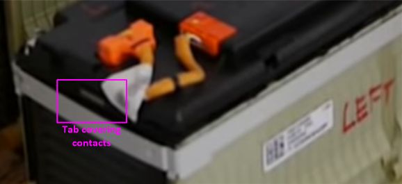
| Gain access to #1 thermistor contacts area | Don't remove black battery-top cover?
| I believe it's unnecessary to remove the black cover on top of the battery. Removal is easy, it just unsnaps, but then you have to be wary of dropping metal objects on the battery tabs.
|
|
| Assess strategy
| At this stage, the #1 thermistor spring contacts are almost visible.
|
|
|
|
|
|
Gain access to thermistor contacts
| Alternatives....
| The thermistor contacts could be accessed by removing the end-plate of the battery.
However, that requires removing the metal strap and the long through bolts (threaded rods?). That would decompress all the battery segments, putting at risk the coolant seals between all battery cells. Some clamping arrangement could be devised to mitigate that problem, but better to avoid it if possible.,
Hence the tab-cutting strategy detailed below.
|
|
| Cut the tab that covers the contacts
| Video: "Dissecting the Chevy Volt's electric drivetrain" https://www.youtube.com/watch?v=00tTckGUv7I has some useful orientation footage, though not for this exact job
Carefully use a knife and/or Dremel to cut away the tab to expose the contacts.
The next photo is cut from a photo in the Prof Kelly post at https://www.gm-volt.com/threads/got-p0c36-code-dealership-says-i-have-to-replace-a-battery-4400-00-help.330381/
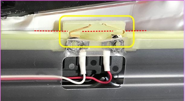
The red dotted line indicates where to cut. I think in Prof Kelly's photo, the plate has been flipped around, and so you would be cutting the tab from the back relative to this photo. If this plate has not been flipped in the photo, then there must be another plate in front of this one, and it's the tab on that plate that you would cut.
Obviously care is needed while cutting to avoid mangling the springs.
| Knife?
Dremel with cutter suitable for nylon-y plastic.
|
|
|
|
|
| Investigate | Caution
| While investigating, proceed in an order which minimizes disturbance to the components. We want to definitively locate the discontinuity, so we want to avoid disrupting the break in a way which might temporarily reconnect it.
|
|
| Examine
| Examine the spring contact area visually. Is it obviously corroded?
|
|
| Measure resistances
| With ohmmeter measure resistance of the various sections of the thermistor circuit.
A. As judged by measuring at the connector X4, is the thermistor circuit still discontinuous?
B. Can you read a sensible resistance when probing the spring contacts? Hopefully yes.
C. Can you determine which contact is at fault? Or is there any possibility that the break is somewhere else in the circuit, (thus won't be fixed by soldering the spring contacts.)
|
|
| Some jiggling
| With ohmmeter attached to the #1 thermistor pins of the battery-top connector, can you restore a sensible resistance by gently prodding one or other of the contacts and getting them to reconnect?
|
|
|
|
|
|
Fix
|
| Since we're guessing that the likely problem is at the contacts, I've listed some steps to attack that.
|
|
| Clean up the contacts | Clean up the contacts and prepare to solder. | Contact cleaner spray, such as Deoxit
Very fine sandpaper. |
| Solder across the contacts
| Solder each spring contact to its mating contact area. It may require some patience to solder upside down.
I would avoid pressing too hard upward on the fixed contacts in the battery top, as we don't know how they are attached in place.
| -- A soldering iron and tip of suitable size.
-- Electronics flux (like in a flux pen) might be helpful, but the flus in flux-core solder should be adequate.
|
| Verify resistance
| Again with ohmmeter attached to the #1 thermistor pins of the battery-top connector, measure resistance. Is it consistent with other thermistor?
|
|
|
| Gently prod the spring contact area and thermistor wires and confirm that it doesn't flake out.
|
|
|
|
|
|
| Tape over opening
| Remove any grease from the area, then cover the hole that was previously cut with tape of some kind
| Need some strongly-adhesive tape wide enough to cover the hole..
|
|
|
|
|
Reassembly
|
| Mostly the reverse of disassembly
|
|
|
|
|
|
| Reconnect harness
| Atop the rear battery, reconnect the orange harness
|
|
|
|
|
|
| Visual check
| Verify all undercover work is finished |
|
|
|
|
|
| Reinistall cover
| Replace cover and bolt it down
Replace screws around the disconnect receptacle.
|
|
|
|
|
|
Reinstallation
|
|
|
|
| Position the battery
| Roll the battery under the car
|
|
|
| -- If car is on a lift, slowly lower the car onto the battery,
-- If car is on jackstands or ramps, slowly jack up the battery into position
While doing so:
a. Observe a few key bolt locations to achieve mating.
b: Closely watch the cables and hoses so that they don't get trapped, and will end up next to their respective connectors.
|
|
|
|
|
|
| Bolt the battery in place
| Install all the bolts.
Torque to spec
|
|
|
|
|
|
| Reconnect
| Reattach cables and hoses.
|
|
| Replace the cover
| Replace the front sheet-metal that covers up the connector area.
|
|
|
|
|
|
| Reconnect 12V battery
| Might be some things to check at this point to verify things are OK?
|
|
| Refill the battery coolant
| -- Tank is in the frunk.
-- Just filling the tank probably won't fill all the little waterways in the battery, so....
-- A comment on Coopers Automotive Volt battery swap video part 2 (https://www.youtube.com/watch?v=WFwXMcxFTV0) says you can command the battery coolant pump ON from a bidirectional scan tool, which should circulate the coolant into the battery.
-- It's likely that just running the car will cause the pump to run and circulate the coolant adequately anyway.
-- The most important factor is to prevent the car from running the coolant heater unsubmerged. But since that is at the bottom level of the battery inside the front bulkhead, it pretty much has to become submerged when you initially fill the coolant.
-- After running the pump (one way or another) recheck the coolant level and top up as necessary
| -- Coolant
-- It's supposedly a mix with DI water, so line up the mix ahead of time
|
| Reinstall the HV battery disconnect
|
|
|
|
|
|
|
Start up
|
|
|
|
| Check for codes
| Using scan tool, just note any existing and pending codes
|
|
| Clear codes
| Using scan tool, clear codes.
|
|
| Run car
|
|
|
| Check for codes
| Proceed accordingly
|
|

 Uploading ....


