Overview
Ivan investigates crank no-start on Genie lift, attributable to misbehavior in the neighborhood of the Ignition/Start controller module. Discussion ensues about how that module works. In particular, what sort of path the Tach signal takes from the input to... wherever it goes.
There was also some conversation on Ivan's Community page (https://www.youtube.com/user/motoYam82/community), where we discussed that dropouts in the tach signal could stem from bad brushes in the alternator.
Referring to the Genie schematic (reproduced below), the tach signal ("STA") is just the center tap of the three phase alternator stator windings.
- The stator produces output from the rotating magnetic field of the rotor windings (aka "field windings" or "excitation windings").
- But the rotor only produces a magnetic field when current is supplied to those windings, and increasing or decreasing that field current is the mechanism by which the regulator adjusts the overall output of the alternator (stator windings).
- The rotor windings receive current via slip-rings and brushes, so if those wear out and become intermittent, so the stator sees an intermittent rotating field, and produces intermittent output current, and also intermittent STA (tach) signal.
- That, we surmised, was that actual cause of the problem Ivan saw.
2020-03-16 Ivan posts that indeed it looks like the alternator is bad and replaced it. https://www.youtube.com/watch?v=cQCHKNC4csw
Videos
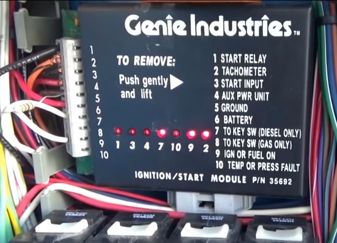
Photos of the Ignition/Start controller module
Reverse engineering from Ivan's photos
Click to expand
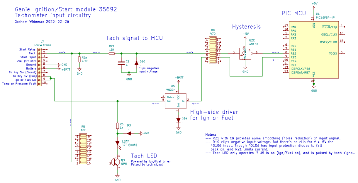
Notes on the schematic
- From Ivan's scope traces: The input tach signal is essentially a 12V square wave (well, probably 13.5V).
- R21 + C9 provide some smoothing of noise. It would be interesting to know the capacitance value of C9 to assess the cutoff frequency.
- D10 clips any excursions below 0V to about -0.6V
- These components by themselves do not decrease the amplitude of the signal. However...
- The 40106 is powered from 5V, so requires input signals with maximum swing from 0V to 5V.
- Clipping the excessive input voltage. The 40106 has input protection diodes which will clip the input to -0.6V to +5.6V, so long as the source of the signal is of high enough resistance to limit the current to what those protection diodes can handle. (Otherwise the input current will burn out those protection diodes, and then the excessive voltage destroys the 40106 input transistors.)
- In this case the input resistance of R21 + R9 does limit the current, to < 1mA. Because of the clipping, the input signal downstream from R21/C9 will have a 0V to 5.6V swing.
- These 40106's built-in protection diodes are intended as a safety feature, for example draining static buildup on inputs that are otherwise not connect (say an input connector is unplugged). They are not intended for use as they are here, as the only clipping mechanism for a signal that always swings outside the required voltage range. (Ie: Genie should have provided a diode clipping to 5V separately, but they would not be the first to get away with this.)
Hysteresis provided by the 40106
- From the schematic above, we understand that the 40106 sees the slightly filtered verbatim input signal from 0V to 5.6V, and input voltage above that is clipped. The verbatim portion means that the module's characteristics for reading the tach signal are just the 0/1 threshold and hysteresis characteristics of the 40106.
- Ivan measured:
- Datasheet for 40106:
- So... Ivan's measurement agrees with the datasheet. Yay Ivan!
- A curious missed opportunity? Designing this circuit so that the 0/1 threshold is around 2.6V, when the input swing is really 12V or more is not necessarily a good idea -- it's highly asymmetrical. We might prefer that the 40106's 0/1 transition detection was applied more in the middle of the input voltage swing, instead of toward the bottom. For example, if the input signal passed through a 12:5 resistive divider, the 12V swing would be reduced to 5V, and the 40106 0/1 detection would apply to the middle of the swing where the noise is less, and any noise (such as the crank-signal dropouts at low RPMs that Ivan saw) is reduced by the factor of 5/12.
- This is suspiciously like the circuit would be if "R2x" was moved to after R21, instead of before (where it doesn't appear to have much of a purpose). OK, this is 5/15, but then again "12V" is really 13.5V. Might this have been the intended circuit:
 ???
???
(The voltages on this diagram are rather approximate -- but they make the point.)
Previously observed
- U1 is a PIC MCU
- U2 is a 40106, hex schmitt-input inverters, almost certainly for conditioning input signals
- Other points of interest
- U3 MIC2951 provides 5V to the PIC MCU and the 40106.
- So whatever hysteresis the tach input is treated with will be at least approx 0.9V, the typical value for 40106 running on 5V.
- It could be more if it turns out that the tach input passes through a resistive divider before getting to the 40106.
- The two VN02H 5-pin ICs are high-side switches (Solid-state relays), and supply power to:
- U4 supplies screw terminal 1 "Start Relay"
- U5 supplies terminals 8 and 9
- Terminal 9 is "Ignition/Fuel-On", which makes sense
- But terminal 8 is labeled "To Key Sw Gas Only". Not sure how that is supposed to work. (And in this particular Genie, despite being Gas, it has the key switch wired to terminal 7, "Key Sw Diesel Only".)
- The component date codes imply the board was assembled in 1999.
Schematic of Genie
Click to enlarge
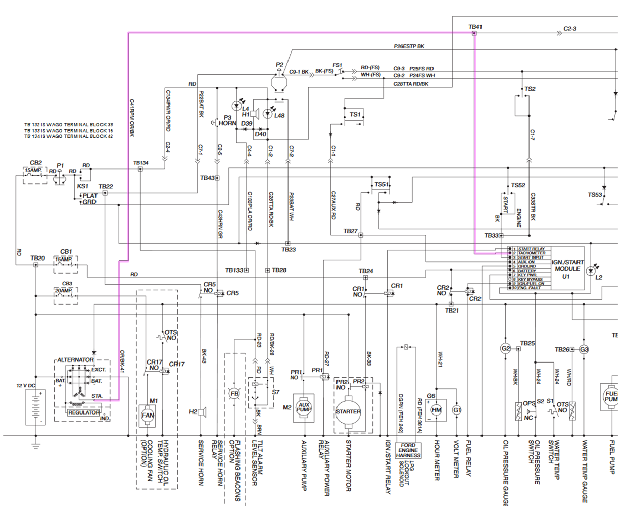
- Genie model Z-60/34
- Schematics:
- 75681.pdf has separate schematics for Diesel and Gasoline ("Ford")
- The Ford models have separate schematics for before and after serial 4546.
- In 75861.pdf Page 6-52 (pdf page 246) seems like a representative schematic for the gasoline model.
Ignition/Start controller module components
- Genie P/N 35692
- Front view of board: https://youtu.be/T6urh_seFoc?t=290
- Board photos on Community: https://www.youtube.com/user/motoYam82/community
- Components visible
- CD40106 hex inverters with schmitt inputs.
- MCU: PIC16C54 RC1/?? 18-pin DIP
- VN02H High-side solid-state relay
- MIC2951 150mA Low-Dropout Voltage Regulator
- Yellow DIP resistor packs are:
- Dale MDP14xx and 16xx series
- 14 = 14 pin, 16 = 16 pin.
- 03 = independent resistors, oriented across the package (In the 14-pin package: pin 1 to pin 14, pin 2 to pin 13, etc)
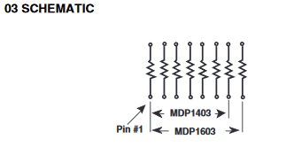
- R9 MDP1403 470 ohm
- R5 MDP1603 10kohm
- 16 = 16-pin
- 03 = independent resistors across the package
- (Dale 1999)
- FWIW, component date codes 1998 and 1999

 Uploading ....


