Created by: gwideman, Jul 14, 2015 4:45 pm
Revised by: gwideman, Sep 11, 2015 1:18 am (49 revisions)
Overview
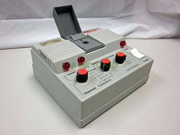
Our local Fab Lab and DIY Bio space acquired an Invitrogen Electroporator II in order to perform DNA transfer experiments. It didn't come with documentation of even how to operate it, nor was any found online. The unit (sold in the late 80's or early 90's?) is no longer supported in any way by Invitrogen, and there was some suggestion that the model was possibly recalled due to hazard potential. (We describe why that might be on accompanying pages.)
For our own use, and for other DIY bio experimenters who may have bagged one of these from eBay and are now in the same boat, we reverse engineered our unit, and describe here how we infer it is to be used, and how it likely behaves in practice.
Orientation
The purpose of the electroporator is to apply a pulse of voltage across a cuvette holding a solution containing cells. The resulting voltage across each cell (or current through the cell?), creates pores in the cell walls, allowing external molecules to flow into the cell.
Inside the cuvette there is a pair of electrodes, with a known spacing between them. By setting the voltage to be applied, an electric field of known voltage-per-mm (V/mm) can be applied. The field is needed only for a brief period of time, so an electroporator applies only a short pulse.
|
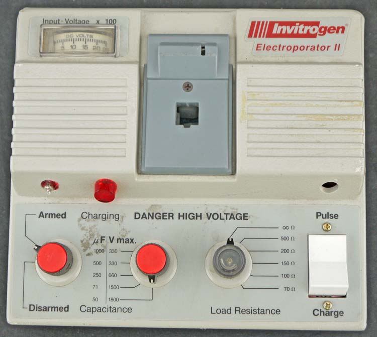 |
| What it's supposed to look like |
Our unit, as it arrived? |
Basic operation
The functions of this model of electroporator revolve around:
-
Making use of an external adjustable high-voltage power supply (typically available in the lab, for electrophoresis) as the source of adjustable high voltage.
- Ie: The manufacturer reduced the expense of the electroporator by not including a power supply.
-
A simple capacitor-resistor circuit to produce a crude but predictable pulse shape.
- Benefits could be argued for a pulse shape having an initial high voltage with later extended period of lower voltage. See references section below.
- The capacitor and resistor are selectable to allow some limited adjustment of the pulse length.
Basic conceptual diagram, highlighting the selectable capacitor, the cuvette (and the resistance of the solution it contains) and an additional selectable resistance in parallel with the cuvette:

The actual unit incorporates a couple more switches that sort of implement a bit of safety and alternatives in the procedure:

The pulse will be delivered to the cuvette only if the lid is closed, and the Armed/Disarmed switch is set to Armed.
Revised model: monitoring terminals
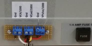
Our revised model adds external terminals as follows:
Terminal
|
Description
|
Gnd
|
Ground (x3)
|
VC4/1000
|
(Test point for technical diagnostic purposes.)
|
VCsel/1000
|
The voltage across the selected capacitor (divided by 1000). Attach a voltmeter here.
|
Vpulse/1000
|
The voltage across the cuvette (divided by 1000). Optionally attach an oscilloscope here.
|
Sequence of user steps
N
|
Step
|
Unmodified unit
|
Embellishment for modified unit
|
1
|
Initial
|
- power supply off
- power supply black and red wires connected to electroporator
-
electroporator switches:
|
Attach digital voltmeter to the Gnd and VCsel terminals on back of Electroporator.
Optionally attach scope to Vpulse terminals
|
2
|
Set electroporator R and C settings
|
- Determine the voltage/mm required at the cuvette, and therefore the pulse voltage needed
-
From the Capacitance knob, note the capacitance ranges that would be permitted at that voltage.
- Higher voltage --> lower capacitance and vice versa
- See later section about confusion in this area
-
With that limitation in mind select Capacitance and Load Resistance to achieve a desirable pulse length.
- See later section on how to calculate pulse length
|
|
3
|
Insert cuvette
|
- Place cuvette in holder
- Close lid.
|
|
4
|
Set power supply to desired voltage
|
- Set the desired voltage on the power supply and turn on the power supply output. See separate power supply instructions below
- Observe that the voltage on the electroporator's meter (= desired voltage/100).
|
|
5
|
Set Armed/Disarmed switch to Armed
|
- In combination with the cuvette lid switch, this completes the path that will allow the pulse, when it is fired, to travel to the cuvette.
|
|
6
|
Ready indications?
|
The following will display:
- Desired input voltage on the electroporator's voltage meter (divided by 100)
- As the capacitor(s) charge, the Armed light will start flashing at a rate which gradually increases until it stays on constantly
- A while later, the "Charging" light will start flashing. It's flashing rate will gradually increase until it stays on constantly
- NOTE! The flashing and later constant glow of these lamps is quite misleading... it only indicates that the capacitors have charged to certain arbitrary voltage thresholds -- it does not indicate that they are charged to your desired voltage, which may be higher or lower than the threshold! (Details below)
- Note: Because the indications are not adequate to determine that the desired voltage is ready on the capacitor(s), you must wait a considerable time longer for the capacitor(s) to charge.
- Yes, that's ridiculous.
|
Watch the digital voltmeter, and note when the capacitor has reached desired voltage.
No need to guess how long to wait!
|
7
|
Pulse!
|
Flip the Pulse/Charge switch to Pulse.
|
|
8
|
Another cycle
|
For another cycle, switch Pulse/Charge back to Charge, and return to step 6 "Ready Indications" (assuming the power supply is still supplying voltage) or to step 4 (set power supply voltage).
|
|
Additional notes
- If you want to discharge the capacitor(s), but don't want to apply a pulse to the cuvette, you can use the Pulse switch while the lid is open. The lid-open switch will redirect the pulse to a dummy resistor (the resistor R12 in the schematic shown earlier).
Electroporator safety notes!
-
Don't stick finger, or objects other than a cuvette, into the cuvette receptacle! There be up to 1800V!
-
Operating the electroporator without the lid and associated cover plate exposes the lid microswitch, whose contacts carry up to 1800V! Don't touch them!
-
Surprise hazard: If the electroporator caps are charged, and the switch is in the Charge position, and you then unplug the input cables at the power supply (perhaps thinking that now the electroporator is safe), those bare banana plugs expose the capacitor voltage of up to 1800V (albeit via a 10k resistor, but can still deliver up to 180mA)
-
2015-09-09 Update: in "Modification 3" I replaced the input cabling and also installed input diodes which prevent current flowing out of the capacitors through the input cable. This should eliminate the hazard at the bare plug pins if the electroporator cable is unplugged at the power supply.
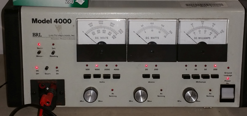
Operating the BRL 4000 power supply
SAFETY WARNING.
- This power supply can output up to 4000V at 50mA, or 1000V at 200mA, where even 50V to 100V at a few mA can be lethal to come in contact with.
- Obviously don't touch the output wires when the power supply is on -- as a habit, don't touch them regardless of whether you think the power supply is on
-
Avoid the following accident waiting to happen: DO NOT leave wires attached to this power supply, where the wires have exposed male banana plugs on the end.
- This specifically applies to the cables normally used to connect to the electroporator!
- To repeat -- when done with the electroporator, do not simply unplug the electroporator and leave the bare plugs lying on the bench! Unplug the cables from the supply as well
- 2015-09-09 Update: in "Modification 3" I replaced the input cabling so that it's permanently connected at the electroporator end. This eliminates the hazard of banana cables connected at the power supply, but disconnected at the other end.
- General electrical safety tip: Only use one hand while working around high voltages (to avoid providing a current path across your chest and heart). Put the other hand out of the way, in a pocket, or similar.
Background information
Three adjustables
The BRL 4000 power supply has three main adjustments:
- Voltage,
- Power (Watts) And remember, Power = Voltage x Current
- Current (milliamps).
I defer exact operation instructions to the next section, but first I want to describe what these three adjustments do.
Essentially, these three adjustments provide three limits which the power supply will obey simultaneously. The power supply will attempt to output as high a voltage, current and power as these three limits permit.
- Usually, the power supply will consistently hit one of these limits first. It is usually your intent to control the power supply by manipulating that limit, and set the other limits higher so that they are not the operative constraints.
-
Very often, you intend to set a particular output voltage, and you regard the power and current limits as safety feature to prevent way over current if you should accidentally short circuit the output.
- For that scenario, calculate the current that you expect the load to draw, and the resulting power, and adjust the current and power settings to some value higher than that.
- Instead, you may intend to deliver a particular current, so use the Milliamp setting to determine that current. You might then set a Voltage limit to avoid delivering a very high voltage if the load turns out to have a higher resistance than expected.
- In all cases, one of the three "At Setting" LEDs tells you which is the limit that currently constrains the power supply.
Under-current safety cutoff
In addition to the voltage, current and power upper limits, we discovered that the power supply has a lower limit on current. It appears that if the load draws less than 2.5 mA, then the power supply disengages its output (switches from DC On to DC Off mode).This is presumably a safety feature, to disable the power supply running when the expected load is disconnected.
More to say about this in relation to the electroporator, below.
Procedure to get a desired voltage from the power supply
The BRL 4000 is intended for use in electrophoresis; using it with the electroporator is a little off its usual application. Some patience seems to be needed to get it to behave.
The BRL 4000 has three modes, which are switched between using the three round black buttons on the left. The present mode is indicated by the LEDs. Proceed as follows:
Mode
|
Push button
|
LEDs
|
Voltage out?
|
Other procedures
|
Adjust voltage etc
|
Set Reading button
|
"Set" LED lit
DC Off lit
|
No voltage at output
|
Adjust the voltage, power (Watts) and current (Milliamps) limits using the three sections of front panel each containing a meter, range selector pushbuttons and adjustment knob. In each case the pushbuttons set a particular full-scale range and you must read a value on the meter using the corresponding scale, and adjust the needle to the desired value using the knob.
Example: To set 1200V, press the 2000V button, read values on the meter using the scale where 2000V is the highest value, and adjust the knob so the pointer points to 1200 (which is the same position as 600 on 1000V scale).
For electroporator use, power can be set to 50W and current to 100mA. (These values are not critical -- higher values will allow faster charging, but lower values limit damage in case of accident. Cleverer values can be thought out depending on voltage)
|
Get ready
|
Norm Reading button
|
Norm LED lit
DC off lit
|
No voltage at output
|
Nothing. (Get other equipment ready.)
|
Activate output voltage
|
Push Start button and hold until DC volts needle rises to near target value, then release
|
DC On lit
|
YES
|
When you release the Start button, the DC On button stays lit.
If you release the Start button, then hear a click, and the output mode changes to DC Off, this indicates that there is insufficient load (2.5mA). Hazard: this may tempt operator to use two hands to operate some other aspect of the equipment while holding the Start button. This is a dangerous way to fix this problem. Operators should train themselves to use one hand only around high voltages. Fix by incorporating a component (probably a resistor) to increase the load.
|
Won't go to DC On!
|
You push Start, nothing happens!
|
DC off lit
|
No, but...
|
If the BRL 4000 output shuts off (DC off LED) while the Electroporator capacitor is charged up, the BRL 4000 sees a voltage on its output (from the capacitor), thinks that is an error condition, and refuses to respond to the Start button and go to DC On mode. You must discharge the electroporator's capacitor to proceed. (You can do this by firing the Pulse switch while in Armed mode. To avoid pulsing the cuvette when firing the Pulse switch, open the cuvette lid.)
|
|
|
____________
|
__________
|
|
Defeating the under-current safety cutoff for use with electroporator
For some combinations of voltage and electroporator settings, the electroporator draws enough current to exceed the power supply's undercurrent threshold, and hold the power supply on. For other voltages and settings, the electroporator draws too little current, especially as the capacitors reach full charge, and this allows the power supply to detect "insufficient load" and to disengage.
We can defeat this behavior by adding an additional resistor across the power supply whose sole purpose is to ensure sufficient load current.
2015-08-16 Modification 2 added a resistor load at the electroporator to draw at least 2.5mA, so long as the power supply voltage is above about 550V
Variations on procedure
One could imagine a variety of different orders of steps. The main things to watch:
Equipment Safety
-
Unlike most equipment, simply operating the knobs on this equipment while it is powered up can harm the equipment itself!
-
Do not turn the Capacitor knob while the capacitors are charged/charging.
- Doing so will cause the switch to short the charged capacitors, resulting in heavy arcing and possibility of welding the contacts of the capacitor switch
- Before Switching from higher VMax (Maximum Input Voltage allowed) to lower VMax positions, reduce the input voltage from the power supply so that it is less than the VMax that you are going to switch to!
-
If the caps have charged to a high voltage, and then you decide to decrease the input voltage, the caps will take a while to discharge to the lower desired voltage
- The electroporator's built-in voltmeter displays the input voltage, NOT the capacitor voltage! (On our modified unit, an external voltmeter does read the actual capacitor voltage.)
-
You can discharge the capacitors without firing a pulse to the cuvette:
- With the Armed/Disarmed switch set to Armed, you can open the cuvette lid and then fire the pulse. The pulse will fire into a dummy resistor load, not through the cuvette. (A good reason to have an operational lid!)
Idiosyncracies in operation
The Capacitance knob is confusing and dangerous
-
The VMax (Maximum Input Voltage) numbers on the capacitance knob tell the operator the voltage which must not be exceeded at the electroporator input (ie: supplied by the power supply).
- The VMax number DOES NOT mean that the electroporator will magically produce that voltage of pulse at the output. The output pulse voltage is entirely controlled by the input voltage (assuming the cap(s) have had time to charge to that level).
- The VMax number DOES NOT mean you have to use a voltage that high. Using a lower voltage input voltage is fine, though you might not get the "charging" light to illuminate -- which is fine if you have confidence that the cap(s) are in fact charged to the desired voltage. (On our modified unit, not a problem -- just read the capacitor voltage on the external meter.)
-
Obviously relying on the operator to avoid accidentally apply a high input voltage when a high C (low VMax) is selected is a very dicey idea. To avoid blowing up the capacitors in such a case, the electroporator does include a protection ("crowbar") circuit whose job it is to detect an inappropriately high voltage at the input (relative to the C selected) and to shut down the voltage actually arriving at the capacitors. Once that happens, it will likely blow the fuse (mounted on the back of the unit). If it doesn't blow the fuse, the shutdown will still require decreasing the input voltage close to zero to clear it.
- There is no special indication that this has happened. However, the Armed and Charging indicators should stop glowing.
- The protection circuit is not very well designed, and should not be relied upon for regular use. (More about this flaw on the electronics page.)
The Charging indicator lamp is misleading
During the phase where the capacitors are charging, the Armed and Charging indicator lamps will start unilluminated, and then later start blinking, after which the blinking rate increases until the lamps are on continuously. An operator might interpret that as "full charged and ready". However this is incorrect.
- The indicator lamps always comes on when the capacitors reach a particular threshold voltage (fixed for each cap switch selection), regardless of the voltage you want (ie: the voltage you set on the power supply).
- For a particular Capacitance setting, using a lower input voltage will cause the Charging indicator to come on later, (because the fixed threshold is reached later). Using a higher voltage causes the Charging light to come on sooner. But again, in neither case does this tell you that the cap(s) have reached the desired voltage.
In our unit, the misleading lights are not a problem, because the attached external voltmeter tells you the capacitor voltage.
Calculation of R, C and pulse length
The pulse shape produced by this instrument has a sharp onset to the maximum voltage, followed by a classic R-C exponential decay.
Salient features:

In which:
- 100% on the voltage axis is essentially the input voltage supplied by the power supply to the cap(s), assuming they have indeed had time to charge to that level.
- Tau is one time constant, the time taken to move 63% toward the final value (ie: decrease to 37% of the initial voltage) and can be calculated as Tau = R x C
- Example: Tau = 500uF x 200 ohm = 100,000 uS = 0.1 sec
-
Note that R in this formula is Rload in parallel with Rcuvette.
- R = 1/(1/Rload + 1/Rcuvette)
- Example: if Rcuvette is 1000 ohm, and Rload is set to 500 ohm, R = 1/(1/1000 + 1/500) = 1/(3/1000) = 333 ohm
-
Needless to say, it may not be easy to determine R for the cuvette. Just measuring it with an ohmmeter may not produce a result that's representative of how conductive the cuvette solution will be when experiencing a high-voltage pulse. Consequently, it is probably necessary to fire some test pulses with some representative test solution while observing the pulse on a scope to see what pulse shape results. From that waveshape, read off Tau, and from that calculate what R must be, given the C you have selected.
- It would be worth experimenting with whether or not measuring the cuvette's resistance with something as simple as an ohmeter does or does not provide a representative resistance when pulsed. TBD!
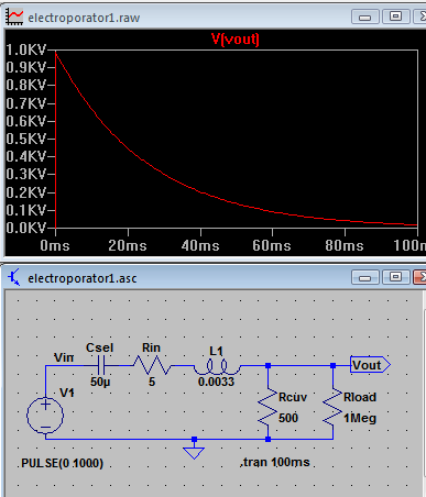
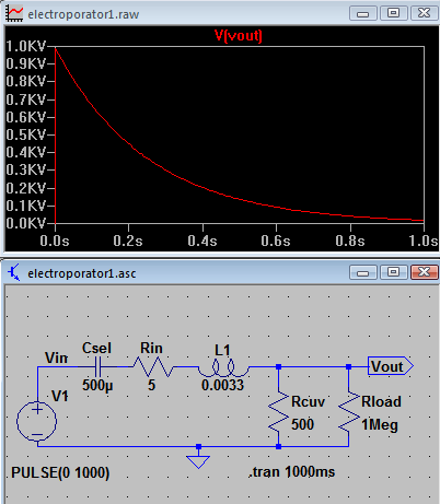
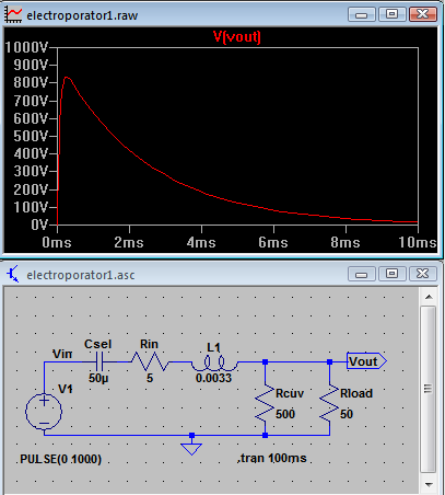
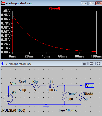
Spice simulations
-
Simulates capacitor charged to 1000V. All plots vertical axes set to 1000V.
- Using a higher or lower input voltage will result in a similar waveform scaled to that voltage.
- Important! On the actual unit, max allowable voltage for 500u is 330V! I used 1000V in the simulation just to make the vertical proportions easy to read
- Note different time axes!
-
Uses Rcuvette = 500 ohms
- Note that in reality, this varies wildly for different solutions.
-
Varies:
- RLoad from 50 ohm to 1 Meg ("infinity")
- C from 50u to 500u
|
50uF
|
500uF
|
RLoad
1M
|
 |
|
500 ohm
|
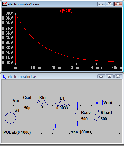
Tau = 50e-6 x 250 = 12.5 ms
|
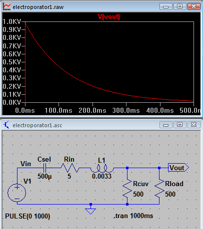
Tau = 500e-6 x 250 = 125 ms
|
50 ohm
|
|
|
Notes:
Simulation component
|
Electroporator component
|
Csel
|
Capacitor(s) selected on the electroporator
|
Rin
|
R15: 5 ohm
|
Rcuv
|
Rcuvette Resistance of the cuvette solution
|
Rload
|
Rload selected on electroporator
|
L1
|
Actually L2
|
- The main waveform shape is determined by C1 in conjunction with the resistance formed by R1 in parallel with R2.
- The effect of L is to somewhat slow the initial rise of the wave, and "round" the peak. This is negligible for most of the range of R and C, though L does come into play where R is low: for Csel = 50u and Rload = 50ohm, the plot shows that the peak is diminished to about 830V. I conclude that the intended purpose of L was not so much to benefit the electroporation as to perhaps reduce RF output (to avoid radio interference) or limit the current surge.
- Thanks to Adrian Clausell who prompted my investigation of the value of L1 and L2 and the SPICE simulation.
Actual Pulse Waveform
In preliminary examination of actual pulse waveforms on a scope:
- the general shape and time constant of the waveform is very close to expected
- the actual initial peak voltage is a little lower than the simulation (say 10%?) and variably so. We've not characterized this completely nor determined the exact cause.
Possible reason for actual peak less than simulation:
- The capacitors have additional resistance, effectively in series.
- We observed some switch bounce -- the initial part of the pulse sometimes showed some jagged teeth instead of rising to a clean sharp peak. Probably as the switch contacts approach one another, the voltage across them is high enough to invite arcing. This partially discharges the capacitor before the switch is fully closed. Likely this effect is more prominent with higher voltages.
Electronics and modifications
Please see other pages, as mentioned in the Overview at top of this page.
Notes and references on electroporation
Mostly from Cameron C:
Some sample protocols. Not sure for what type of cells, nor what specific solution. Most seem to use parameters in this range:
- 2mm cuvette
- 2.2 kV (ie: 1.1kV/mm field)
- Measured cuvette R = 500-600 ohm
- Load R set to 600 ohms (result: R = 300 ohm)
- C = 50 uF
-
Time constant observed: ~25ms
- Calculated T = 50E-6 x 300 = 15 ms. Close? Suggests Rcuvette may not be as low as measured?
Taku's info:
AC's info
-
http://www.cytopulse.com/pulseagile.html
-
Discussion of two purposes:
- Creating pores in the cells
- Moving molecules into the cells
- While not overheating the solution
- ... and consequent merit of initial short high-V pulses and later longer low-V pulses
Other links:

 Uploading ....