Originally created by: gwideman, Aug 1, 2015 3:41 am
Overview
This page describes modifications which we implemented to our Invitrogen Electroporator II, to address several issues:
- Mods round 1:
- correct some design flaws which compromised its robustness and safety,
- add some terminals via which to safely monitor its capacitor voltage and pulse waveform.
- Mods round 2
- Revise the capacitor chain for higher capacitor values at the two highest-voltage-capable settings
- Add additional load resistor at the input to defeat the under-current cut-off feature on our power supply.
- Mods round 3:
- Temperature within the electroporator case causes SCR crowbar protection circuit to fire unnecessarily (and blow fuse, costing actual money).
- Safety of the high-voltage jumper cables from power supply to electroporator.
This page follows on from other pages describing:
The "electronics" page discusses several flaws in the design, which will be useful background for understanding the revisions described on the current page.
Mods 1. Danger reduction and output monitoring
This modification aimed at:
- revising the capacitor chain so that the caps would operate within their specifications.
- Adding monitoring points, so that that an operator can observe capacitor voltage before pulsing, and observe the pulse shape on a scope.
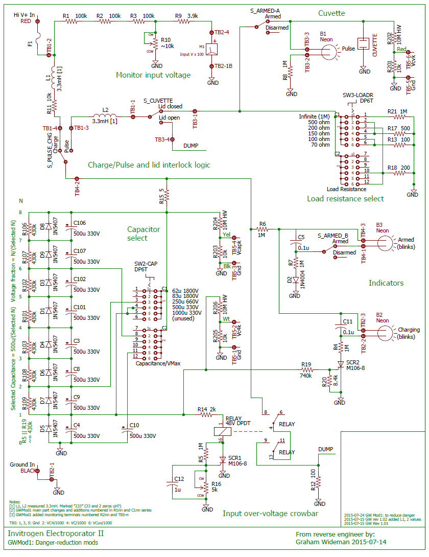
PDF version: Invitrogen_Electroporator_II_gwmod1_schematic.pdf
Notes:
- Modification adds or changes components numbered as follows:
- Main changes: C1nn, R1nn
- Additions for monitoring: R2nn, TB5
Capacitor chain remediation
1. Replace_C1,2,7,6_with ~500u >330V_parts
This:
- Makes the initial charging voltage distribution even
- Increases the allowable voltage on these four caps
- In combination, so far as the initial applied voltage, allows all the caps to operate within ratings
- To the extent that the protection circuit provides some protection against input over-voltage, this protection now also protects C101,102,107,106.
Side effects: Increases the capacitance and voltage ratings as follows:
Switch posn
| Max V to avoid overvoltage
on initial period of Pulse
| Modified C
| New allowable
capacitor voltage
|
50u/1800V
| 1666
| 62u
| 2640 [*]
|
71u/1500V
| 1168
| 83u
| 1980 [*]
|
- [*] I'm not suggesting actually using those voltages, as other parts of the circuit might not withstand them.
2. Add resistors in parallel with capacitors
- Nominally 430k, (unless the existing ~430k path around C4 is modified).
- To be clear: Add 430k resistors across all the caps in the chain, except for C4, which is already paralleled by 430k.
- Can be soldered on the bottom of the board at the capacitor pins.
Remediation simulation
- Modifications: C1,2,7,6 replaced with 470u. Resistors added in parallel with caps to distribute the voltage (here labeled R1..R8. ooops)
- Long-term simulation shows steady even distribution of voltage, well below capacitor rated voltage.
- The 430k resistors draw 550uA, P = (550E-6)^2 * 430E3 = 0.13W (total about 1W for 8 resistors)
Remediation parts
Capacitors
Capacitor physical sizes, for considering replacements. Since the capacitors are located cheek-by-jowl, there's little to no room for larger diameter.
Cap
| Value
| Diameter
| Height
| Lead spacing
|
C1,2,6,7
| 500u/330V
| 0.875
| 1.75
| 0.25 (offset from center line about 0.125)
|
C3,4,8,9
| 330u/250V
| 1.0
| 1.57
| 0.4 (on center line)
|
Available height: 1.8" only!
Possible ~500u >330V parts with 1" diameter and 0.4 lead spacing. 500uF is not a commonly available value, hence the 470uF choice instead. Also these kinds of capacitors generally have a tolerance (manufacturing variability) of 20%.
Digikey lists more, but not in stock.
Resistors
430k 1/2W
Component mounting
- New capacitors fit the locations of the removed capacitors
- Resistors across the capacitors mounted on non-component side of the board
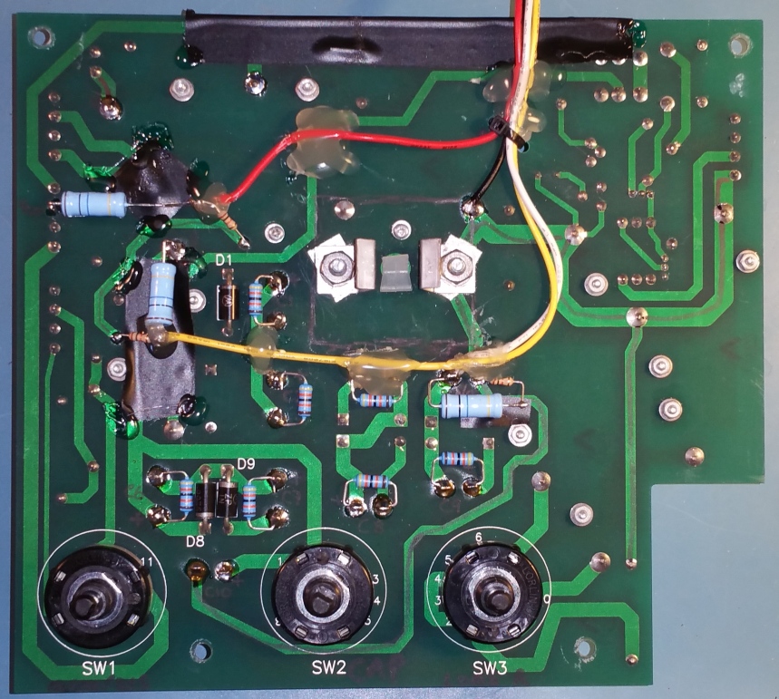
- board photo shows additional components and wiring for the monitoring circuitry, described next.
- Not apparent from this view angle: some glue blobs are quite thick, to hold off-board wires above the board away from high-voltage traces.
Monitoring terminals
Add voltage divider circuits to bring out various voltages (divided to safe range) so that they can be observed on a voltmeter and/or scope:
- the capacitor chain voltage (as selected by the Capacitance switch) -- to show what pulse height to expect, and that caps have finished charging
- the cuvette voltage -- so that pulse shape/duration can be observed on a scope.
- the C4 voltage -- which the electroporator uses for the Charging light and "protection" circuit.
- Mainly for diagnostic and pedagogical purposes :-)
Specs
- Divide-by-1000
- 10 Meg input R
- 10k output R (1% error with 1M instrument, neglecting capacitance)
Worst case I = 2000V/10 Meg = 0.2mA. P = VI = 2000 * 0.2E-3 = 0.4W
Select 10M 1W resistor good for >2000V:
Implementation
In each case, a resistive divider consisting of 10M and 10k resistors was used. These were soldered to the non-component side of the PCB, as shown in the picture above.
We added some tape and strategically placed blobs of hot-glue, both to add some insulation over high-voltage traces, and to fasten wires in place in routes above the board (away from high voltage) and around the cuvette well. (Alternative: get hook-up wire that's rated for >2000V)
The off-board wires routed through a keyhole slot cut in the lower edge of the case; if the PCB needs to be removed, the terminal board can come with it and separate from the case.
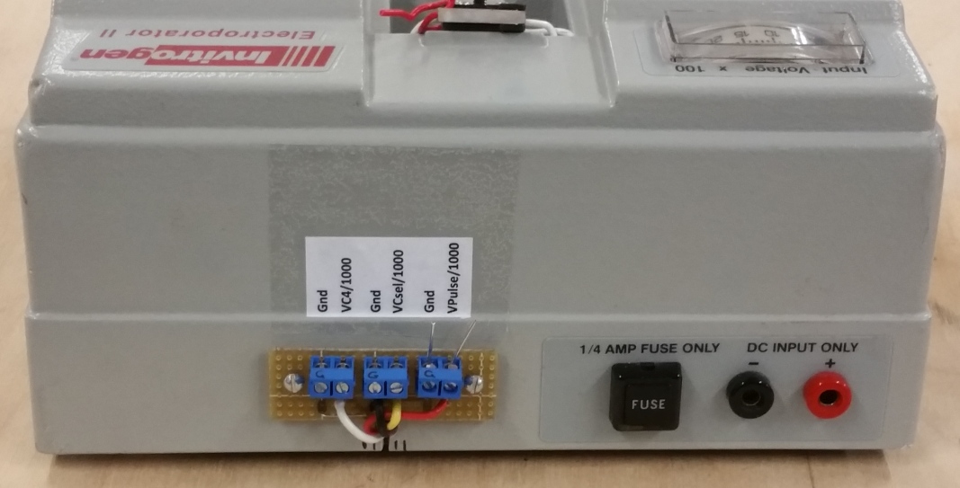
Rear terminals
Mods 2: Capacitor chain; PSU under-current cutoff
This set of modifications addresses:
- Revising the capacitor chain to provide larger capacitances for the two lowest C/highest V settings.
- Defeating the power supply's under-current safety cutoff.
Schematic
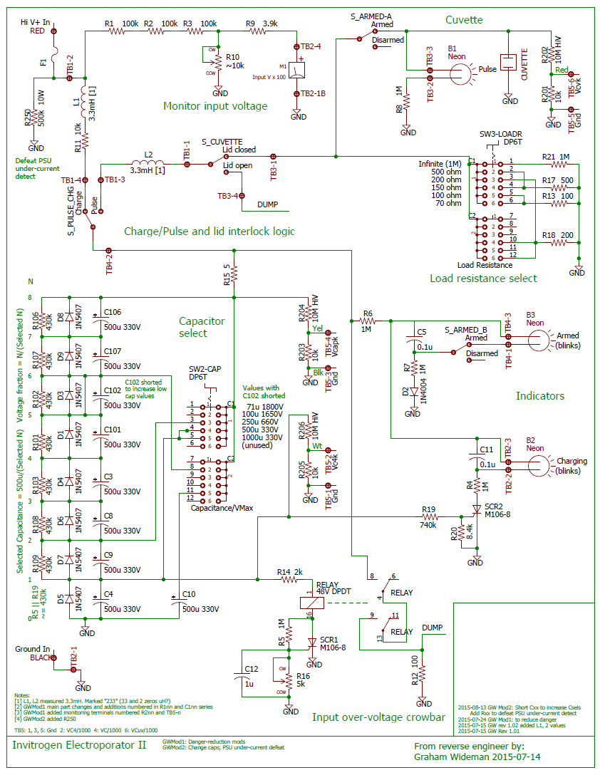
PDF version: Invitrogen_Electroporator_II_gwmod2_schematic.pdf
Capacitor chain revision
One of our main users :-) is focused mainly on higher voltages (~1500), and is using a cuvette solution with relatively low resistance. Hence this user values higher capacitance at the higher voltages. A quick modification to that end (not requiring removing the PCB and all its wiring attachments) is to short C102 (old C2), which can be done on the component side by shorting D3. The resulting capacitances/voltage ratings:
Old switch
posn
| Max V to avoid overvoltage
on initial period of Pulse
| Modified C
| New capacitor
voltage rating
|
50u/1800V
| 1666
| 71u
| 2310 [*]
|
71u/1500V
| 1168
| 100u
| 1650
|
[*] Not recommended to use over 1800V, since other parts of the circuit were only intended originally for <1800V.
Defeating the power supply's under-current detection
We have had a problem where our power supply, when used with the electroporator, cuts off at seemingly arbitrary times.
It turns out that this BRL 4000 power supply has an under-current safety cutoff which disables the power supply when the load consumes very little current (<2.5mA), presumably under the assumption that this condition signifies an accidental disconnection (possibly with loose output wires exposed on the workbench).
For some combinations of voltage and electroporator settings, the electroporator draws enough current to exceed the power supply's under-current threshold, and holds the power supply on. For other voltages and settings, the electroporator draws too little current, especially as the capacitors reach full charge, and this allows the power supply to detect "insufficient load" and to disengage.
We can defeat this behavior by adding an additional resistor across the power supply whose sole purpose is to ensure sufficient load current.
(See R205 on GWMod2 schematic.)
Some notes and rough calculations
- The power supply appears to require >=2.5mA load to stay engaged
- For capacitance switch settings 250u-60u, the resistance across the input, as the capacitors reach full charge, is dominated by the 300k ohms of R1+R2+R3.
- We would like the power supply to stay engaged at voltages down to 500V (Taku requirement).
- R = V/I = 500/2.5mA = 200k. Rneeded || 300k = 200k = 600k || 300k; Rneeded = 600k. So choose 500k for even lower voltage usability
- Power = V^2/R = 1800V^2/R = 1.8^2 E6/0.5 E6 = 6.4 W. So choose 10W, high voltage (2kV or better)
- Specs: 470k to 510k, 10W, 2kV
Candidate part(s):
Modifications installed
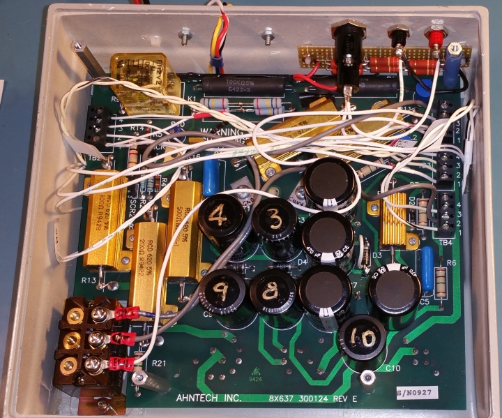
- The 6 resistors comprising R250, the 500k resistor for PSU under-current defeat, is located next to the + and - inputs and fuse holder.
- The jumper which changes the capacitor chain is a white wire across D3.
Mods 3: Over-voltage protection; HV input cables
Responding to
- Over-voltage protection triggered, blowing fuse. (Relay clicked, R12 was quite hot, fuse was blown.) This happened while input voltage was not over-voltage, unit was sitting idle. But, had been on for tens of minutes, and the new under-current defeat resistors were contributing to elevated temperature. (And case is not ventilated.)
- High temp may have precipitated reduced threshold on over-voltage circuit
- Some concerns vis-a-vis the wiring from high-voltage power supply to electroporator.
Remediation
Just some interim notes:
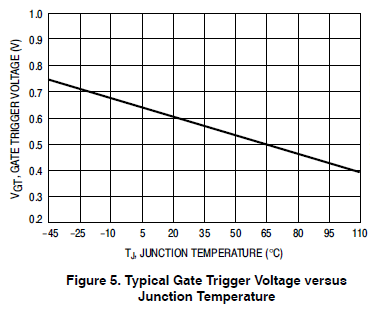
- The SCR trigger voltage temp sensitivity makes it unsuited in general as a precise threshold detector. No easy way to fix this.
- Usual SCR crowbar circuit uses a zener diode as the voltage-detecting element. However, in this case a ~350V zener would be needed. Such is very expensive, and large (due to power dissipation).
- So original design here depends on simple resistive voltage divider, with result compared to the SCR threshold, which is temperature sensitive.
- Increase threshold on over-voltage crowbar
- Adjust R16 to lower value. (Note before and after R measurements, or V at SCR1 gate)
- Consider appropriate fuse rating
- Case says 0.25A. Actually installed was 1/32A slo-blo.
- Needs to be high enough rating to withstand actual charging
- Needs to be low enough rating to blow, given power supply current limit.
- Moved PSU under-current defeat resistors to external ventilated case to reduce heat inside case
- Also drilled some vent holes in the case anyway, to help vent the power resistors such as R1, 2, 3.
- Fuses. Fry's search for fuses, then 3GA
- HV leads
- Replace banana jacks on rear of electroporator with permanently-connected HV leads
- On power-supply end, attach dual-banana plug, so if HV+ is connected, so is Ground
- Add input rectifier (2000V reverse rating, or 2 x 1000V), to prevent current in the electroporators's capacitors from flowing out of the power input cables, in the event that the power plug is disconnected from the power supply, and thus able to come in contact with metal or humans.
Schematic following mod 3:
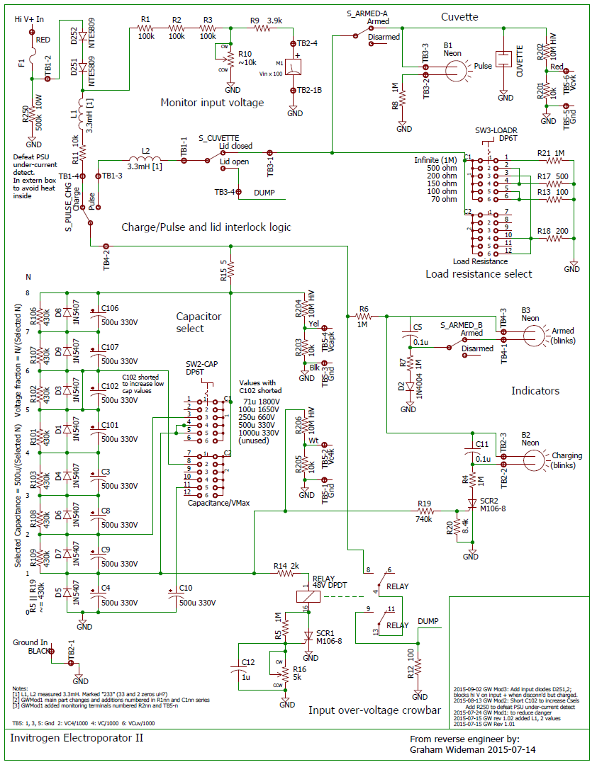
PDF Version: Invitrogen_Electroporator_II_gwmod3_schematic.pdf

 Uploading ....
