Originally created by: gwideman, Jul 16, 2015 5:41 pm
Overview
A teardown of the Invitrogen Electroporator II, schematic diagram, and critique of some problems with the design.
From this exercise we derived an understanding of how the machine was intended to behave, and how it actually behaves.
Electronics
Here is the complete schematic of the electroporator, as near as I have been able to determine from carefully tracing the PCB.
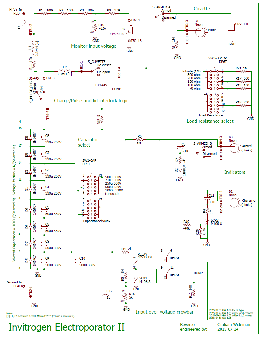
PDF download: Invitrogen_Electroporator_II_schematic.pdf
Bear in mind that there may be more than one revision level in circulation (this board already says "Rev E"), so don't take this schematic as gospel.
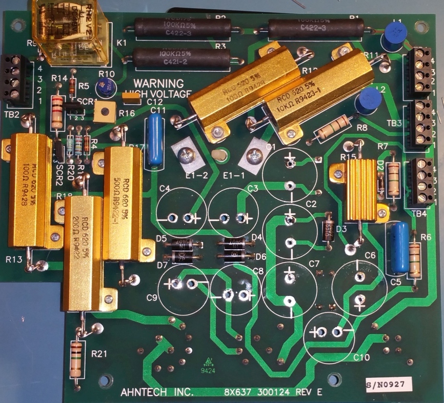
PCB front and rear views
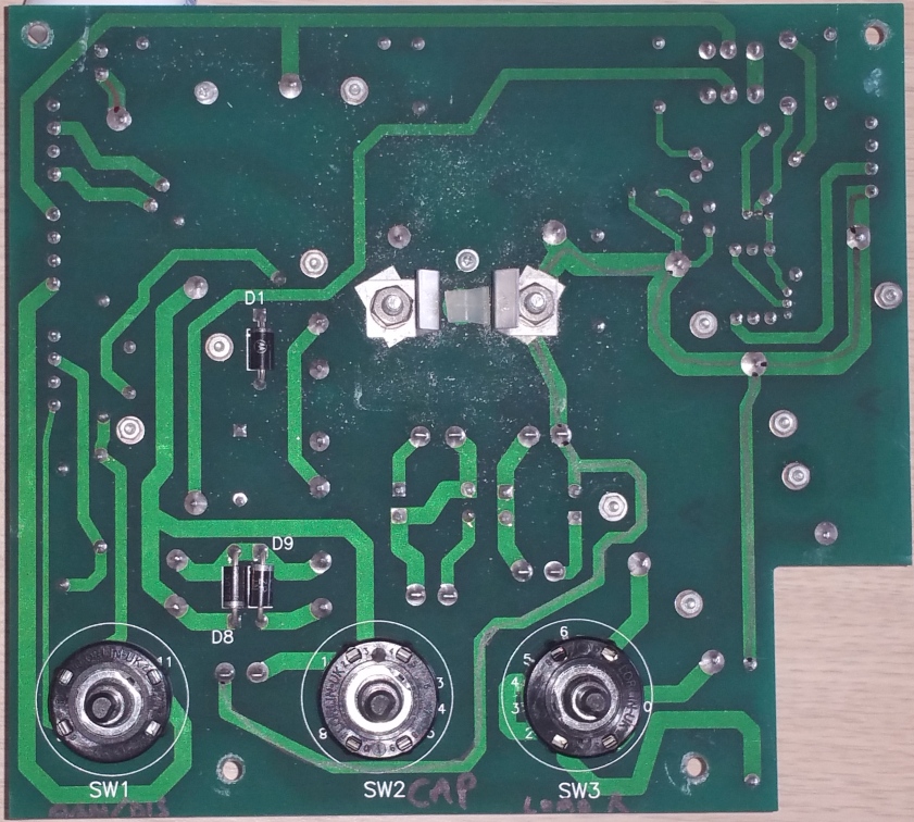
Component-side view, capacitor chain caps removed to reveal traces:
Issues with the electronics design
There are a number of concerns with the design of this equipment, described in the sections which follow.
The capacitor chain has multiple issues
- The voltage ratings of the capacitors have been miscalculated, and are inadequate
- The chain omits voltage-balancing resistors, leading to indeterminate and dangerous voltages
These are described in the following sections.
The capacitor chain voltage ratings have been miscalculated
The capacitors selected by the Capacitance switch are arranged in a chain. Several positions of the switch select two or more of these capacitors in series, which distributes the high input voltage across the series of capacitors. This composes a combined capacitor which able to withstand a higher voltage, but at the expense of a smaller combined capacitance value (the normal effect of capacitances in series).
For example, two 500u 330V-capable capacitors in series combine to form a 250u capacitor, capable of withstanding 660V, provided some concerns are addressed.
The chain includes two different types of capacitor: the four "lower" ones are 500u 330V, while the "upper" four are 330u 250V. Unfortunately, when arranged in series, the overall applied voltage (initially) distributes according to the inverse of the capacitor values, so the lower-value capacitors will see a higher proportion of the overall voltage. So much so that, in some switch positions, the lower-rated capacitors will see considerably over their maximum rating when VMax is applied at the electroporator input.
What do capacitor voltage ratings mean? These relatively high-capacitance capacitors are of "electrolytic" construction, and have characteristics described here, for example:
www.surgecomponents.com/capacitors/aluminum_electrolytic/pdfs/Precautions-and-Guidelines-for-Aluminum-Electrolytic-Capacitors.pdf
In general, the rated voltage should not be exceeded on a regular basis. Doing so results in break down of the insulation between the layers of the capacitor, leakage current, and if sustained, considerable heat and possibly an explosion. Consequently engineers normally choose a capacitor voltage rating that exceeds the intended operating voltage by a substantial margin. As the linked article notes, it is acceptable to exceed the rated voltage for brief periods, but even that briefly-allowable "surge" level is only on the order of 10% above rated voltage.
|
Needless to say, this also has implications for the crowbar circuit which is intended to protect the capacitors, discussed later.
For ease of analysis, we can treat the capacitor chain as an equivalent chain of equal capacitors of 1000u, which will allow us to quickly determine equivalent capacitance and voltages seen by each actual capacitor. Cresult = Cindividual/N (See also N values on the schematic.)
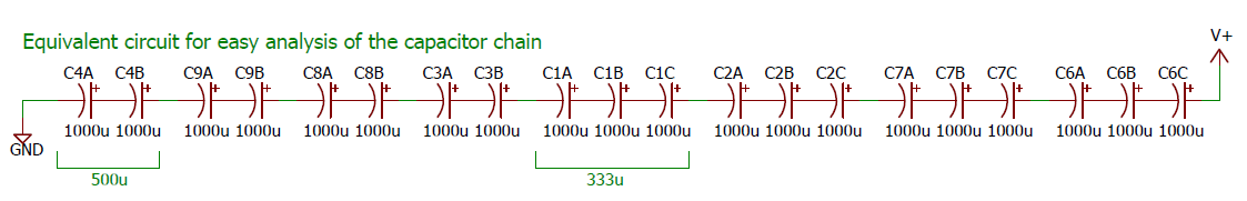
Example: When the switch is in the minimum capacitance, highest Vmax position, all capacitors are include. Hence:
- Cselected = 1000u/20 = 50u (agrees with knob legend)
- V across each 1000u cap = Vmax/20 = 1800/20 = 90V.
- V across 500u = 2 x 90V = 180V. That's fine, the 500u caps are rated at 330V
- V across 330u = 3 x 90V = 270V. The 330u caps are rated for only 250V. Oops.
At the "71u Vmax = 1500V" setting the situation is worse:
- Cselected = 1000u/14 = 71.4u (agrees with knob legend)
- V across each 1000u cap = Vmax/14 = 1500/14 = 107V.
- V across 500u = 2 x 10⁷V = 214V. That's fine, the 500u caps are rated at 330V
- V across 330u = 3 x 10⁷V = 321V. The 330u caps are rated for only 250V. Oooops.
Vmax values which do and don't don't abuse the 330u caps:
Switch legends
C Vmax
|
C4, 9, 8, 3
(500u, max allowed 330V)
cap voltage @Vmax
|
C1, 2, 7, 6
(330u, max allowed 250V)
cap voltage @Vmax
|
Cap-friendly
Vmax
|
50u 1800V
|
180V
|
270V
|
1666V
|
71u 1500V
|
214V
|
321V
|
1168V
|
250u 660V
|
330V
|
na
|
660V
|
500u 330V
|
330V
|
na
|
330V
|
1000u 330V
|
330V
|
na
|
330V
|
The capacitor chain omits needed voltage-distributing resistors
The problems described so far regarding the capacitor chain assume a distribution of voltages in ideal capacitors with no other components in the picture.
The analysis so far reflects how the capacitors would behave if there are no other current paths. However such is not the case:
-
There is a current path around C4
- R14 -> Relay coil -> R5 -> R16 -> Ground, so approx 1Mohm current path.
- R19 -> R20 -> Ground, approx 748k path
- Each capacitor in the chain has some leakage current, which we might represent as a parallel resistance
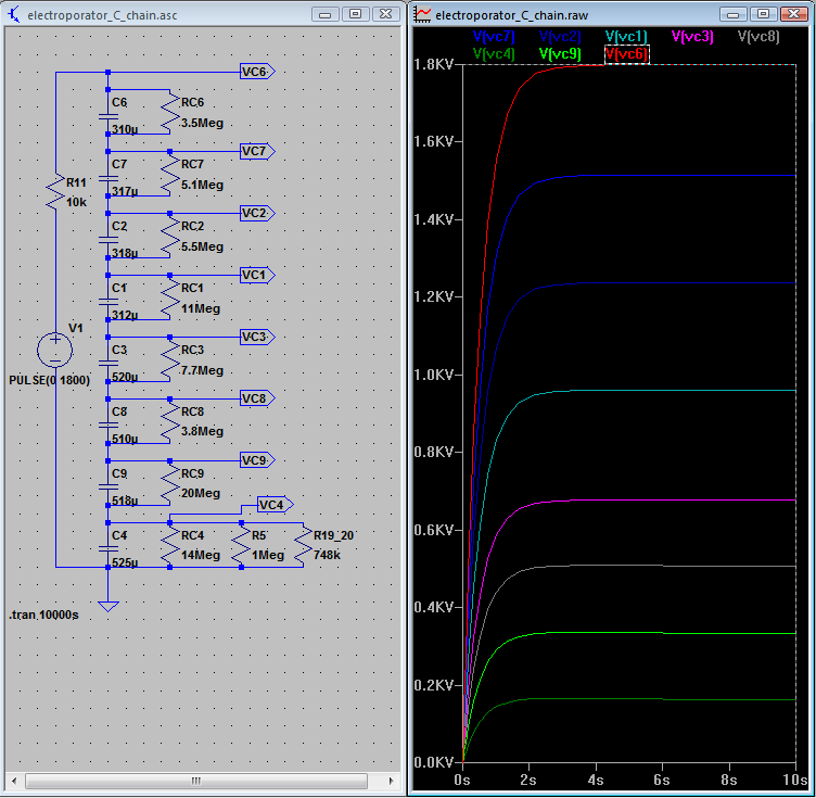
Here is a simulation, showing the actual capacitor capacitances and leakage resistances as measured in our unit.
|
|
Simulation of actual components. Simulation of first 10 secs after applying 1800V
|
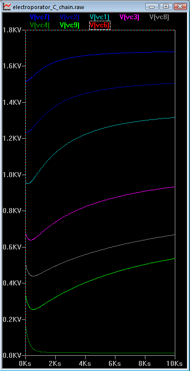
Longer term simulation. 1 hr = 3.6k secs
(C6: red line is obscured by left and top axis.)
|
The plot of 10 seconds of simulation clearly shows how the capacitors quickly adopt a share of the overall voltage inversely proportional to their capacitances. (The charging time is perhaps optimistically quick, as it assumes the power supply current limit set above 180mA at 1800V. It's likely that actual charge rate is slower.)
The plot showing almost 3 hours worth of simulation shows how at an early stage the voltage on C4 drops (because of R14-R5-R16 and also R19-R20). This drags down all the other voltages, though the relative proportions of the other caps remains similar.
Then, as time elapses, the capacitors slowly charge/discharge toward voltages proportional to their leakage resistances (and unrelated to their capacitances!). This leaves C9, which happens to have particularly low leakage, with something like a 500V share, and C1 also has a large share (and lower rated voltage!).
In reality, it is likely that capacitors experiencing considerable excess voltage will leak more (ie: their resistance will decrease), which will reduce their share. But this is certainly not a phenomenon to depend upon.
In brief, this is a textbook case of why we don't apply capacitors like this.
Dealing with voltage distribution in a capacitor chain
There are two issues to address:
1. Initially, the voltages across the individual capacitors will apportion according to the inverse of their capacitances.
2. After some time, the voltages across the individual capacitors will apportion according to their (leakage) resistances and any other resistance in parallel with each.
The designer has to ensure that in neither of these conditions are the voltage ratings of the individual capacitors exceeded.
We already noted that the Invitrogen's capacitor chain violates the voltage ratings of some of the capacitors on initial charging. The worst excess is 320V applied to a 250V rated capacitor. That's a design error, but capacitors can usually withstand 20% or more over voltage, so we would not necessarily expect an immediate failure, particularly since this occurs only for a specific switch and voltage combination.
Now for the longer time period, where voltages apportion according to resistances associated with each capacitor. The standard way to deal with this is to place a resistor in parallel with each capacitor, so that the resulting chain of resistors divides the voltage evenly (or at least according to capacitors' rated voltages, if these differ). The added resistors should have low enough resistance that the capacitor's leakage resistance influences the added resistorl divider chain minimally, yet large enough that it doesn't drain an unduly large current around the capacitor network.
Example discussion of this issue:
For our electroporator, it would have been a reasonable idea to add a resistor of around 1 M in parallel with each capacitor (adjust to suit rated voltage). That would result in an 8M path around the entire chain: 1800V/8M = 225 uA, and < 0.05W per resistor, probably acceptable.
However, C4 is already bypassed by 1M || 748k ~= 430k. Leaving those resistors in place would commit us to using values in that same neigborhood to parallel each of the other caps. The chain would need to be 4 x 430k + 4 x 325k ~= 3M, resulting in 600uA, and 0.15W per resistor, still not awful.
The capacitor chain protection circuit
Compounding the problem with unrealistic Vmax values, the protection circuit doesn't provide the level of protection that was likely intended.
The protection circuit monitors the voltage across the "bottom-most" capacitor in the chain (C4), since that capacitor is always involved whatever the selector switch position. The protection trigger threshold must obviously be some voltage higher than the normal voltage range advertised for the switch position which selects just C4, which is 330V. Yet if the selector switch is set at one of the lower overall capacitance settings (50u or 71u) which includes some or all of the 330u capacitors, those caps would see 330 x 1.5 = 495V just when C4 is at 330V. That's double their 250V rating, so even if the protection threshold is set at VC4 = 331V, the protection circuit does not protect the 330u capacitors.
I have actually measured the protection circuit threshold on our unit, and it triggers at about 390V. This is 20% over the rating of the 500u/330V capacitors, which is a design failure, but probably won't cause the capacitors to fail if applied only occasionally. However, on the 50u and 71u settings, 390V on C4 corresponds to 585V on the 330u/250V capacitors, even more egregiously over their rating.
Voltages across capacitors when protection circuit triggers:
Cap switch legends
C Vmax
|
C4, 9, 8, 3 voltage @
protection trigger
|
Caused by
input V
|
C1, 2, 7, 6 (330u/250V)
cap voltage
|
50u 1800V
|
390V
|
3900V
|
585V
|
71u 1500V
|
390V
|
2730V
|
585V
|
250u 660V
|
390V
|
780V
|
na
|
500u 330V
|
390V
|
390V
|
na
|
1000u 330V
|
390V
|
390V
|
na
|
Protection circuit summary:
- Given the present capacitor values, the Vmax values listed on the capacitor-select switch should be reduced for the 71u and 50u positions, as shown in the preceding table.
- The protection circuit is useless for protecting the 330u/250V capacitors in case the input voltage is accidentally set far above the 1500V (should be ~1160V) or 1800V (should be ~1660V) levels.
- The protection circuit may indeed be useful for protecting the 500u/330V capacitors from the almost inevitable operator mistake of turning the capacitor selector switch to a high-C low-V position while charging with the input power supply set to suit low-C high-V.
The switch ratings are suspect
A number of the switches (and the relay) handle voltages that can be up to 1800V, yet are rated only in the low 100's of volts. This has the potential for considerable arcing (and resulting wear of the contacts).
Of particular concern is the rotary capacitor select switch, which not only may have up to 1800V across its contacts, but when turned will short across one or more capacitors resulting in a very large current if the capacitors are charged. So probably -- DON'T DO THAT!
Switch bounce?
To actually fire the all-important pulse, this equipment just uses a simple switch -- the Charge/Pulse rocker switch. This is a little surprising, since mechanical switches are notorious for "bouncing" -- making and breaking the circuit several times over fractions to tens of milliseconds, before settling to a solid "On" state. Further, this switch sees voltages up to 1800V, with considerable potential for arcing, and thus damage on the switch contacts, increasing the risk of bouncing later in life. Given the concern over the shape and duration of the pulse (on the millisecond time scale), this raises questions regarding whether a mechanical switch will reliably deliver a clean pulse, or will the switch bounce mess things up?
In initial scope observations, we have seen some clean pulses, and some with bouncing. However, we have yet to exercise this thoroughly, knowing what we know now about the various behaviors of this unit.
The off-board wire rating is suspect
Some of the off-board wiring carries up to the full 1800V (notably to the Pulse switch and the cuvette microswitch). These wires are marked "M22759/11-22", which is rated for 600V. Draw your own conclusions.

 Uploading ....