Overview
Reverse engineering the window regulator position encoder for this video:
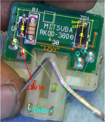
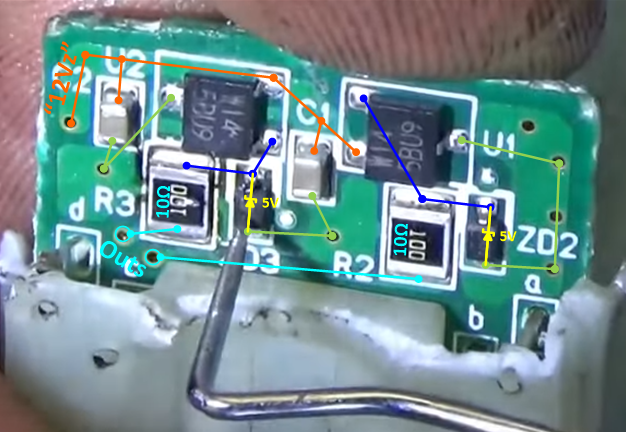
PC Board traces
Pin side: https://youtu.be/GPMcQO_htjY?t=1543
Sensor side: https://youtu.be/GPMcQO_htjY?t=1618
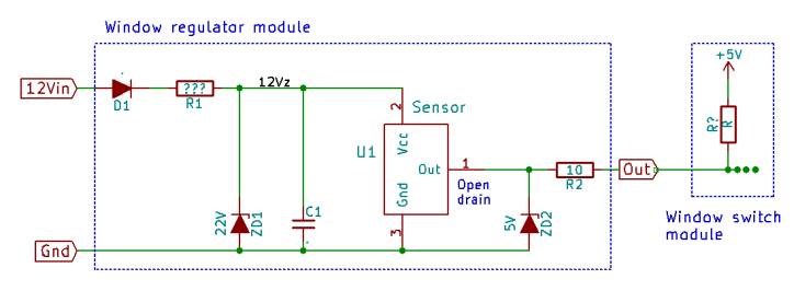
Schematic
(Shows only one of the sensors and outputs):
Notes:
1. "12Vz" is just a label for the 12V supply "regulated" by Zener ZD1. Though...
2. The SMD part number of ZD1 translates to a 22V Zener diode, which is unexpected in this location. It could be there to protect against voltage spikes on B+ damaging U1. Or it could be there to regulate the input voltage to within U1 limits if this module is used in a 24V application. Or the SMD translation is wrong -- SMD Ids are ambiguous.
3. I did not find a hit for U1 and U2's markings W14 5BU9, but they are likely similar to Allegro A1250 and others. (Though possibly different pinouts).
4. Actual voltage of ZD2 and ZD3 is not known, but might well be around 5V in order to set peak value of output waveform, and/or to avoid damage to downstream circuits that expect 5V input.
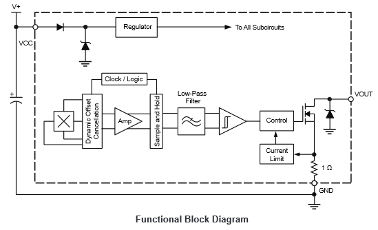
Representative hall-effect sensor IC
- Allegro A1250 "Hall-Effect Latch / Bipolar Switch"
- This is almost certainly not the actual sensor in the Subaru regulator, but I included it to show an example open-drain output circuit.: When on, capable of pulling the voltage near to ground; when off, relies on the downstream receiving circuit to provide a pull-up voltage and resistor.
- Device is in SOT23 package, like the one in the Subaru (so similar heat disipation and power-handling capability.)
- ... and output current limit is 30-60mA
Accounting for damage upon probing with test light
- Assume one side of test light is connected to Battery+
- Assume say a 200mA test lamp
- Probing the connection marked "Out" in the schematic will result in a current as follows:
- When sensor output is "on" (low), current flows through the output transistor (MOSFET) to ground
- 200mA exceeds the current capability of that transistor, in the example Allegro A1250. (Might or might not be true of the Subaru's "W14 5BU9"s.)
- When sensor output is "off" (high), current flows through zener ZD2.
- 5V x 200mA = 1W, which almost certainly exceeds the dissipation capability of a component that small.
- So that could explain the failure during testing. (But is based on the speculation that ZD2 and ZD3's zener voltage is 5V.)

 Uploading ....