Overview
The somewhat canonical Arduino Uno R3, and the many other variants of Arduino, have multiple supply voltage input and voltage regulator paths. This article explores them, and identifies some hazard situations.
Arduino Uno R3 schematic rearranged
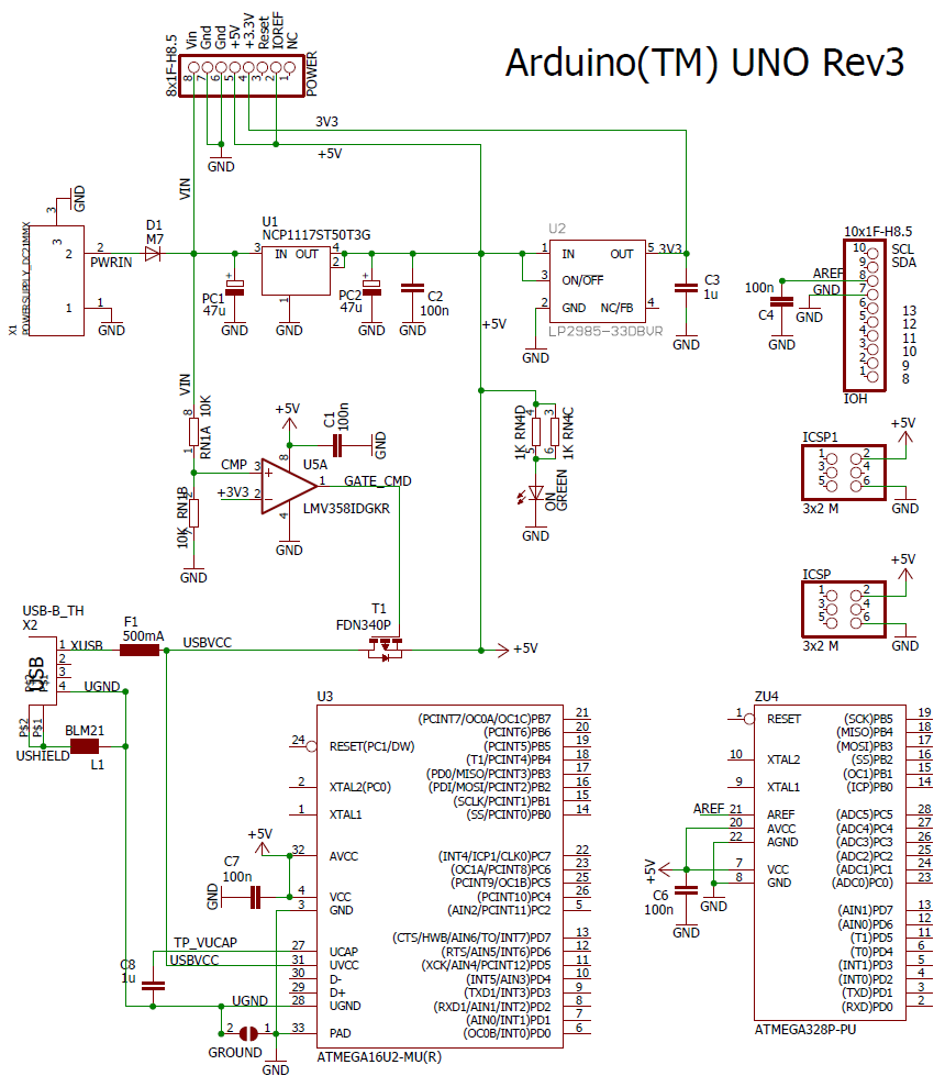
We can rearrange the Arduino Uno R3 schematic to make clearer the relationship between the various supply voltage inputs and regulators. Note that different Arduino models have different power input arrangements, as do partial clones and related boards from other vendors. So the discussion here is only representative.
The schematic below shows only the power inputs, voltage regulators, and the main regulated voltage destinations. (Click to expand).
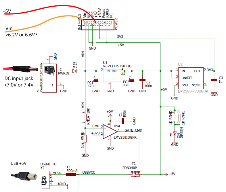
The next schematic focuses just on the inputs and regulators, and shows the four plausible supply voltage inputs.
Notes on each input
Input
| Discussion
|
USBVCC
| Supplies power to Arduino when connected by USB cable to computer or USB power plug. Disabled by T1 if power at sufficient voltage is supplied via DC jack or VIN (but note idiosyncrasies discussed below).
|
PWRIN DC Jack
| The mechanically easiest way to supply power when using Arduino separate from a computer. This input has protection diode D1 which protects the Arduino in case the DC plug is wired backwards. But D1 requires that be 0.8V-0.9V above VIN to operate.
|
VIN (Power header)
| A main purpose of this pin is as an output to supply VIN to shields, so that shield can draw substantial current unconstrained by the max current available from Arduino's regulator. Also VIN's higher voltage, may be important for the shield's features (eg: servos or motors).
However, VIN can alternatively be used as an input, provided user ensures that wiring or of VIN and Ground is never swapped (no protection diode).
|
| +5V (Power header) | This pin is primarily to supply +5V to shields. However, it can be used to provide power to the Arduino, provided it is well regulated.
|
Some salient component properties
Component
| Property
| Description
| Comment
|
D1, type M7 (SMD 1N4007)
| Forward voltage drop
| 0.7 to 0.8V @ 50-100mA @ 25degC
|
|
U1 NCP1117ST50T3G 5V regulator
| Drop-out voltage
| @100mA: 0.95V (typ) 1.10V (max)
@500mA: 1.01V (typ) 1.15V (max)
| Onsemi datasheet
|
U2 LP2985-3.3V regulator
| Drop-out voltage
| @10mA: 40-90mV
@150mA: 280-350mA
| TI datasheet
|
Arduino as a whole
| Current drain (no accessories attached)
| About 40mA measured
|
|
Main questions of interest
1. Voltages required at VIN or PWRIN (DC jack) to properly operate U1?
- VIN > 5V + 1.1V (dropout) = 6.1V Increase to 6.2V for loads closer to 500mA
- PWRIN > VIN + 0.8 (diode forward drop) = 6.9 to 7V.
BUT see also the "Two supplies" question below!
2. Insufficient input voltage: What happens with insufficient input voltage for U1's drop-out voltage spec? This happens with depleting batteries, for example.
Does U1 output just decrease proportionately? With less regulation capability? Or does U1 shut down?
Not characterized on Onsemi's datasheet. To be determined by experiment.
3. Two supplies: What happens when two different supplies are connected? This happens when alternating between programming (using USB) and running from battery or other supply.
- U5A along with T1 is intended to arbitrate between power supplied by USB and power supplied via VIN or PWRIN.
- But this doesn't cover all situations. Elaborated below.
USBVCC switching
Op amp U5A, configured as a comparator, switches GATE_CMD low when input CMP < 3.3V. That condition turns on T1 (P-channel MOSFET FDN340P), essentially shorting USBVCC and +5V nodes, permitting current to flow in either direction.
Conditions that disable T1:
- CMP > 3.3V, which happens when:
- VIN > 6.6V
- PWRIN (DC jack) > 7.4V
Hazard: If power is supplied by USB and also one of VIN or PWRIN, then there are ranges in which USBVCC remains enabled by T1, and both supply voltages are trying to drive the +5V node:
- VIN between 6.1V and 6.6V, or equivalently
- PWRIN between 6.9V and 7.4V
The main concern here is current flowing back through the USB cable to the attached computer, with unknown consequences for the computer's USB power supply.
All combinations of two power sources examined
Here are all combinations of power supplied to two Arduino Uno R3 inputs.
USB
| na
|
|
|
|
|
|
| DC Jack >7.4V | DC disables USB
| na
|
|
|
|
|
| VIN > 6.6V | VIN disables USB
| If DCJack > VIN+0.8, then DCJack prevails, may damage VIN source.
| na
|
|
|
|
| DC <7.4V | USB enabled. Regulator +5V output fights USB 5V, possible damage to USB source. | (nonsense)
| DCJack < VIN + 0.8V. VIN supplies regulator, minimal current drawn from DCJack.
| na
|
|
|
| VIN < 6.6V | USB enabled. Regulator +5V output fights USB 5V, possible damage to USB source. | DCJack > VIN+0.8, DCJack prevails, may damage VIN source. | (nonsense)
| If DCJack > VIN+0.8, then DCJack prevails, may damage VIN source. | na
|
|
| +5V | USB enabled, two sources conflict. Possible damage to USB source or 5V source.
| Two sources conflict. Possible damage to 5V source. | Two sources conflict. Possible damage to 5V source. | 5V regulator operating below dropout, so probably little or no conflict
| 5V regulator operating below dropout, so probably little or no conflict | na
|
| USB | DC Jack >7.4V | VIN > 6.6V | DC <7.4V | VIN < 6.6V | +5V |
Particular challenges
The preceding table identifies a number of hazard situations, each of which might crop up in some scenario or another.
Of particular interest are the challenges of using batteries, while developing code over USB.
- Running an Arduino from batteries at all, given that battery voltages don't relate nicely to the thresholds noted, especially bearing in mind the battery voltage change during its discharge life.
- For example, a 4 x Alkaline "1.5V" battery pack varies from about 5.6V down to 4.4V. So it can't supply 5V per se, and isn't a high enough voltage to connect to a regulated input.
- A "6 x 1.5V Alkaline battery pack" varies from 8.4V down to 6.6V. Would need to be connected to VIn (not DC Jack) in order to consistently power the Arduino, and avoid conflict with the USB-supplied power (when battery voltage < 7.4V)
- So far as I can see, there is no scenario where the USB input takes over supply of power to the Arduino (relieving the load on the battery).
- This is bad from the point-of-view of developing code on a host PC while attached to the Arduino. (Batteries drain.)
- Might be good where the batteries are called upon to supply additional attached devices (such as servos) that might overload the USB power source.
Alternative strategy for battery power
Instead of connecting batteries directly to the Arduino, one can instead use the batteries to power a small DC inverter boost/regulator module. This way, A 4 x "1.5V" AA battery pack, which has plenty of capacity (mAH) for many applications, can be used to produce a consistent 6.8V to apply to VIn, (or 7.6V to apply to the DC Jack). This will keep the Arduino's input voltage in a range which avoids conflicting with USB power when USB is plugged in. The battery can be switched on and off to avoid draining the power when USB power is available.
A further refinement would add wiring direct from the batteries to significant loads (such as servos or motors) that draw considerable current, but are not too fussy about voltage.

 Uploading ....