Overview
A few years ago, I reverse engineered an Invitrogen Electroporator II. On discovering some problems with the design, I set about adding some improvements. I published this on the web. Once in a while I get inquiries about this. Sometimes from people interested in performing electroporation on the cheap, and wondering whether they should obtain one of these old units, or possibly use its design as the basis of a unit they could build for themselves.
So, herewith, some notes.
The objectives and mechanism of electroporation
I am no expert on the cellular biology, but here's the gist.
- The goal is to insert molecules (typically DNA) into cells. If successful, the cells will replicate, complete with the inserted DNA. And ultimately, you have a population of cells with some new characteristics provided by the DNA.
- So, starting with cells floating around in a solution containing the molecules to be inserted, the trick is to open pores in the cell wall, through which those molecules might flow.
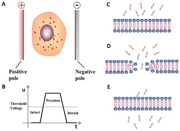
- As the figure shows, pores can be opened by applying an electric field (hence "electro-poration").
- Figure D shows the crucial piece: the electric field prompts the lipids that form the cell wall to wrap their hydrophilic ends (the interior and exterior surfaces of the cell wall) around to form an opening in the wall.
- The molecules of interest enter the cell (transfection).
- The electric field may also help move the molecules.
So the parameters of interest at the cell's scale are:
- The voltage difference across the cell wall, from interior to exterior of the cell. The Sengel and Wallace paper discusses voltages in the neigborhood of 100 to 300millivolts. I don't know how representative this for different cell types.
- That trans-cell-wall voltage is related to the voltage gradient (V/mm) in the solution in the neighborhood of the cell.
- My conjecture: Since the resistance in the solution, and in the interior of the cell are likely quite low relative to the cell wall, almost all of the voltage across the cell will appear across the two walls. That is, the voltage across each cell wall (at the left and right side of the cell oriented as in figure A) is probably half of the voltage across the entire cell. (Half, because there are two walls in the path of the voltage gradient -- one on each side of the cell.
- If so, Vwall = (Voltage_gradient * diameter_of_cell)/2
- To put it another way, if one knows the trans-cell-wall voltage desired, then multiply by two and divide by the cell size to discover voltage gradient needed. Example below.
- Particular voltage waveform over time. From various literature, including that it seemed evident that the technique benefits from a voltage gradient waveform, in which an initial high gradient opens the pore, and then a smaller gradient holds it open, and finally a removal of the gradient allows the pores to seal, and the cell to return to normal. (Ie: figure B is overly simplistic.)
- Applying a sequence of such patterns might improve success. It was not clear to me if that improves success on individual cells, or on the population.
- Some papers use dozens or hundreds of pulses.
- Some protocols talk about an AC pattern -- that is to say, a pattern where the voltage not only steps between different values, but also reverses polarity.
- Applying too high a gradient (too high a trans-cell-wall voltage) could cause an opening that is irreversible, and destroys the cell.
- Apply a pattern or sequence of voltage pulses could heat the solution, damaging the cells via heat. This could occur with high voltages (across the solution), and a low-resistance solution, permitting high current to flow, and thus overall high power.
Simple electroporator calculations
Supposing the target cell type is a bacterium with diameter 1 um (1 micrometer), and the desired trans-cell-wall voltage is 250mV.
- Voltage across cell: 250mV x 2 = 500mV
- Gradient in neighborhood of cell: 500mV/1um
- Voltage across a 2mm cuvette: 2000um x 500mV = 1000V
So we would like a voltage waveform which starts at 1000V.
Perhaps we also know that we'd like the voltage to be applied for only 10ms, after which we want, say, only 100mV trans-cell-wall voltage (ie: 400V across the cuvette), for the subsequent 40ms.
Can we get that with a simple R-C electroporometer? Only very approximately.
Here's what we can do with an R-C unit:
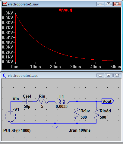
Obviously this uses the exponential decay of a capacitor discharging through a resistor to approximate a "first high, then medium" voltage pattern.
- The peak voltage is set by the input power supply voltage (in the case of the Invitrogen)
- The time course of the decay is set by the combination of R and C (here 50u and 500 ohms in parallel with 500 ohms, as explained on page Invitrogen Electroporator II ).
- R is partly set by the resistance of the solution in the cuvette, (assumed to be 500 ohms in the simulation shown here). That's annoying for two reasons:
- The resistance of the solution varies wildly according to the salinity of the solution. But you presumably want to set the salinity for best cell health, not in order to achieve a particular resistance.
- The resistance can be quite variable from trial to trial.
- Because the cuvette size (here 2mm between electrodes) is so huge compared to the cell size, you are obliged to work with very high voltages in order to achieve a suitable voltage gradient.
- Danger!
- Relatively expensive components
- Relatively specialized components, if you want to devise a smarter (non R-C) electroporator.
- Working with significantly smaller electrode separation eases the voltage requirements
- Working with larger cell sizes means lower voltage required at the cuvette (2mm) scale, because the voltage across the cell (still, say, 500mV) is for a larger size (say 10um) for gradients in the range of 500mV/10um, or only 50V/mm (so 100V across a 2mm cuvette).
Observations
A primitive R-C electroporator like the Invitrogen does do something to cells that could result in electroporation, but in most regards it is thoroughly unhelpful.
There is nothing in the biology or physics of this experiment procedure that requires the waveform to be dependent on the solution conductivity (resistance). Electroporation can be quite hit-or-miss, so it's important to be able to iterate the procedure over a range of parameters (voltage, time, solution variations), and to know with confidence what the equipment did in each trial so that you can associate each result with known conditions.
Having the waveform change when you change solution just makes that iteration inconsistent and frustration.
Not only does the Invitrogen have this incapacity to enforce consistency of the applied voltage pattern, it does nothing to help you monitor either the starting voltage, or the waveform.
- Key point: If you are stuck with a primitive R-C electroporator, then at the very least add the capability to monitor these two parameters:
- Monitor the voltage on the capacitor before you fire the pulse.
- Monitor the waveform so that (a) you see the time course that was applied, and (b) that time course is a slightly indirect measurement of the solution resistance.
- If your electroporator provides voltages in above say 100V, then in order to use an ordinary meter and oscilloscope to monitor it, you can use a resistive voltage divider to tap out suitably lower voltages. We made this modification to our Invitrogen, so see the modifications page for an example.
Since the days of this type of unit, transistors (MOSFETS) capable of switching high voltages have become readily available, and controllers to sequence switching (a la Arduino) are a dime a dozen. So in concept, it is eminently possible to design and build something that produces a well-controlled and repeatable waveform suitable for electroporation. (And it would surprise me if nobody had done so.)
This is especially true for larger cells, or where the electrode separation is smaller, both of which would call on an instrument to deliver much more tractable voltages.
Comment on the vagueness of some electroporation discussions
I have seen a number of papers and read other commentary where the narrative discusses electroporation parameters in terms like "with my cells I use X voltage and Y capacitance", as though that's a complete enough spec to mean something. It does not.
- If a narrative doesn't state the spacing of the electrodes (ie: size of the cuvette, if used), then it doesn't communicate the voltage gradient applied to the solution, and hence doesn't tell the voltage across a typical cell, which is really the basis that one might discuss with others, who could be using different electrode spacing.
- If the cell size is not mentioned, then, again, we can't tell what voltage is applied across the cell.
- If the narrative doesn't state the resistance of the solution in the cuvette, then the R in the R-C curve is not stated, and nothing can be understood about the duration of the waveform.
- Which, within the plausible range of solution conductivity and settings, is apt to vary over several orders of magnitude.
Other links

 Uploading ....